1gSpace Store
ACEP Advanced Telemetry
ACEP Advanced Telemetry
Couldn't load pickup availability
ACEP Advanced Telemetry
Mission Data and Subsystem Analysis Portal
ACEP Advanced Telemetry provides subscription access to the protected telemetry portal for the Alpha Centauri Exploratory Probe (ACEP). The portal organizes mission data by operational domain, allowing subscribers to inspect spacecraft state, subsystem margins, communication status, autonomous-control behavior, scientific measurement channels, and technical reference material from one integrated environment.
The portal supports detailed observation of ACEP mission state, event timing, resource evolution, subsystem coupling, communication geometry, survey acquisition, and long-duration operational trends. Users can inspect current telemetry, compare related domains, review historical behavior, configure reports, and consult the Manual without reducing the dataset to a public summary format.
The interface is optimized for 4K full-screen operation at 100% browser zoom and 100% OS display scaling. Smaller displays remain usable, but the primary layout is designed for detailed inspection, continuous monitoring, and mission-room presentation.
Overview
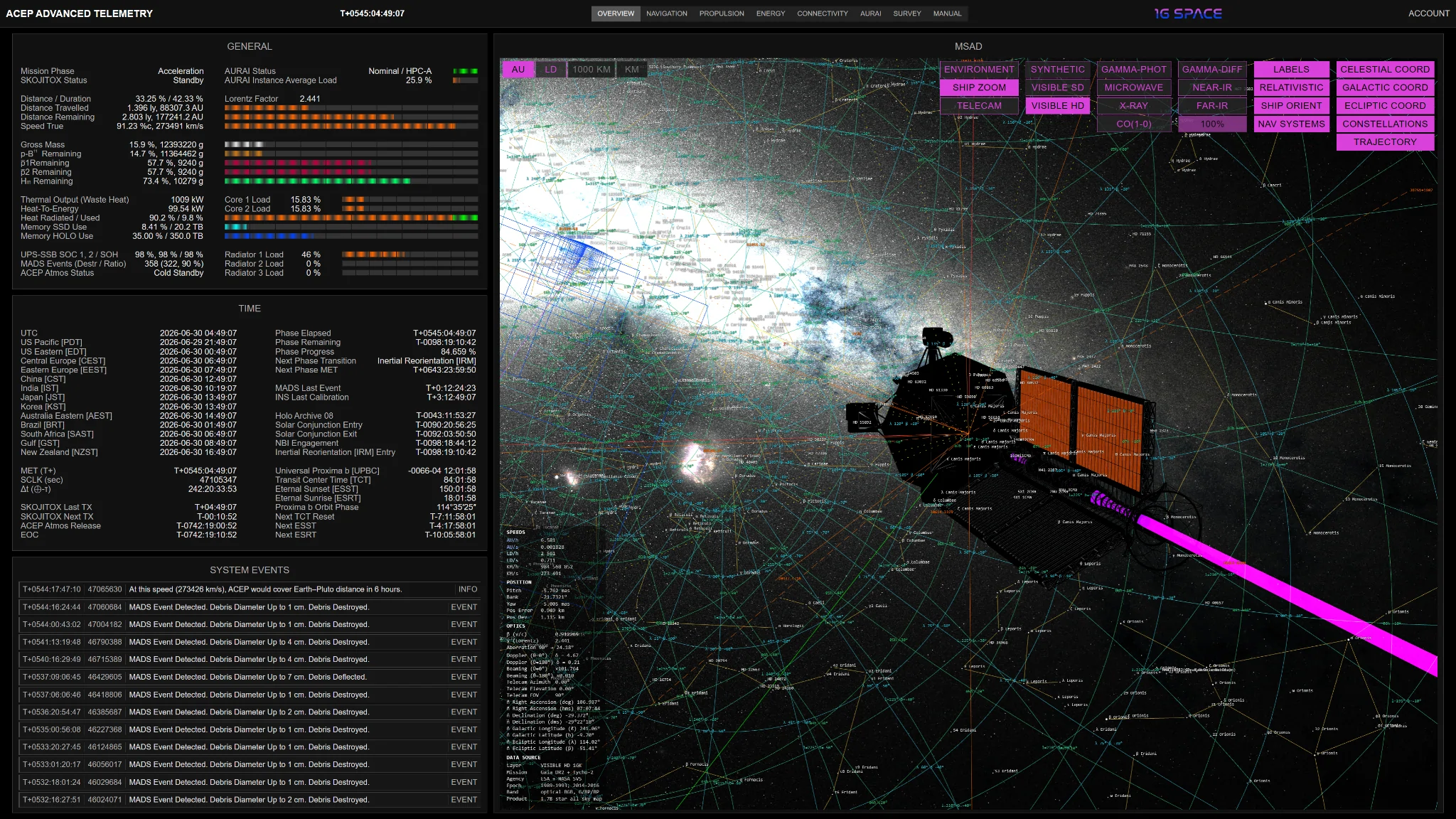
The Overview domain is the primary consolidated spacecraft-state page. It combines the general mission condition, UTC and spacecraft-time references, event chronology, resource status, thermal state, onboard processing state, and the Mission Situational Awareness Display into one first-level operational picture. It is intended for rapid recognition of mission phase, system margins, recent events, and present spacecraft context before moving into the specialized subsystem pages.
The MSAD portion is the highest-density situational layer in the portal. It presents the nominal 1 g Earth-Proxima b transfer line, the actual navigated path, cross-track deviation, attitude axes, event markers, selectable range gates, and spacecraft-relative viewing modes. It also supports environment, ship-zoom, and telecamera-aligned inspection, allowing the user to move from interstellar route geometry down to vehicle-local orientation and pointing context.
- General spacecraft state, mission phase, resource balance, gross mass, fuel reserves, DCMCAAFR load, waste heat, storage use, AURAI status, MADS event count, UPS-SSB condition, ACEP Atmos status, and radiator loading.
- Time-domain status including UTC references, multiple Earth time zones, spacecraft MET, SCLK, accumulated Earth-ship time offset, phase elapsed/remaining, scheduled events, SKOJITOX transmission timing, ACEP Atmos release timing, and Proxima b orbital timing references.
- System Events feed with MET and SCLK event timestamps, live event insertion, MADS debris-interaction records, event type classification, and operational notes derived from current flight conditions.
- MSAD mission geometry with ideal trajectory, actual trajectory, deviation vector, ship-fixed axes, route gates in AU, LD, 1000 km, and km, mission-event markers, and selectable trajectory overlay control.
- MSAD sky context with celestial, Galactic, and ecliptic coordinate grids, constellation lines, Galactic equator, deep-sky object labels, star catalogue layers, and multiple scientific sky backgrounds.
- Relativistic MSAD modes showing aberration, Doppler-related apparent sky compression, forward/aft optical factors, beta, Lorentz factor, Telecam pointing, RA/Dec, Galactic, and ecliptic boresight coordinates.
- NAV SYSTEMS overlay with Star Tracker fields of view, tracker boresight marks, XNAV pulsar references, ship-pulsar connection rays, lock/degraded/rejected timing states, and solution-observability context.
- Vehicle-context rendering for ACEP model attitude, radiator heat state, magnetic-nozzle exhaust plume, SKOJITOX emitter orientation, docked or released ACEP Atmos state, and camera-pointing vector in multiple astronomical frames.
Navigation
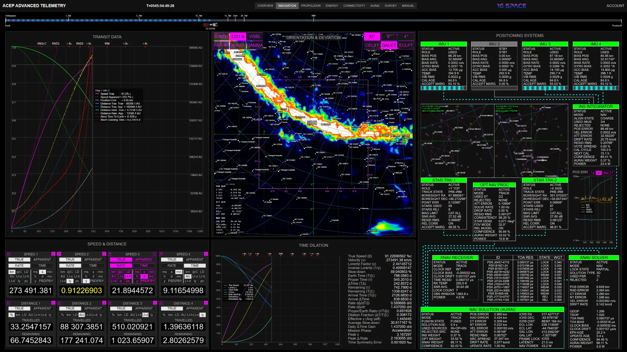
The Navigation domain presents ACEP's long-baseline flight state as a coupled relativistic-navigation console. It combines route progress, transit geometry, true and apparent velocity, distance conversion, time dilation, orientation, cross-track deviation, and the fused navigation solution into one domain. The page allows direct comparison between Earth-frame coordinate quantities, spacecraft proper-time quantities, and apparent ship-frame quantities.
The navigation stack is not limited to a single position readout. It separates the trajectory problem into route progress, velocity/distance interpretation, optical attitude reference, relativistic time behavior, and positioning-source quality. INS, optical Star Tracker, OPT NAV processing, XNAV pulsar timing, and AURAI fusion are all exposed as independent contributors so that source disagreement, drift, residuals, latency, and final confidence can be evaluated directly.
- Progress Slider for the full Earth-Proxima b transfer, including true route completion, contracted apparent distance, ACEP position marker, heliopause reference, Oort reference, abort-return milestones, and IRM midpoint marker.
- Transit Data graph showing the full 1 g transfer in spacecraft proper time, with true speed, apparent speed, true and apparent travelled distance, true and apparent remaining distance, position error, abort time to Earth, abort coasting time, MADS events, and mission-phase markers.
- Speed & Distance modules for true and apparent speed, rate/time forms, travelled and remaining distance, hold/lock behavior, and unit switching across engineering, astronomical, and relativistic scales.
- Orientation & Deviation display centered on the Proxima Centauri reference direction, with 32, 8, and 4 deg FOV modes, celestial/Galactic/ecliptic grids, starfield and sky-background modes, constellation references, attitude marker, course vector, and deviation frame.
- Time Dilation panel for Lorentz factor, inverse gamma, clock-rate fraction, accumulated Earth-ship time offset, proper time, Earth-frame time, remaining proper/Earth time, peak gamma, peak temporal-divergence rate, and symmetry error around IRM.
- Positioning Systems architecture with four IMUs, INS integrator, two Star Tracker optical fields, OPT NAV PROC, XNAV receiver, pulsar table, XNAV solver, position-error history, and final NAV SOLUTION from AURAI.
- Source weighting and diagnostics for INS, OPT, and XNAV, including position error, radial/cross-track/normal-track error, attitude error, source spread, drift rate, update rate, latency, frame lock, ICRS/ecliptic/Galactic coordinates, and confidence.
- Historical inspection through movable timeline markers and graph readouts, allowing past navigation state, velocity threshold crossings, abort geometry, and mission-phase transitions to be reviewed against the same proper-time reference.
Propulsion
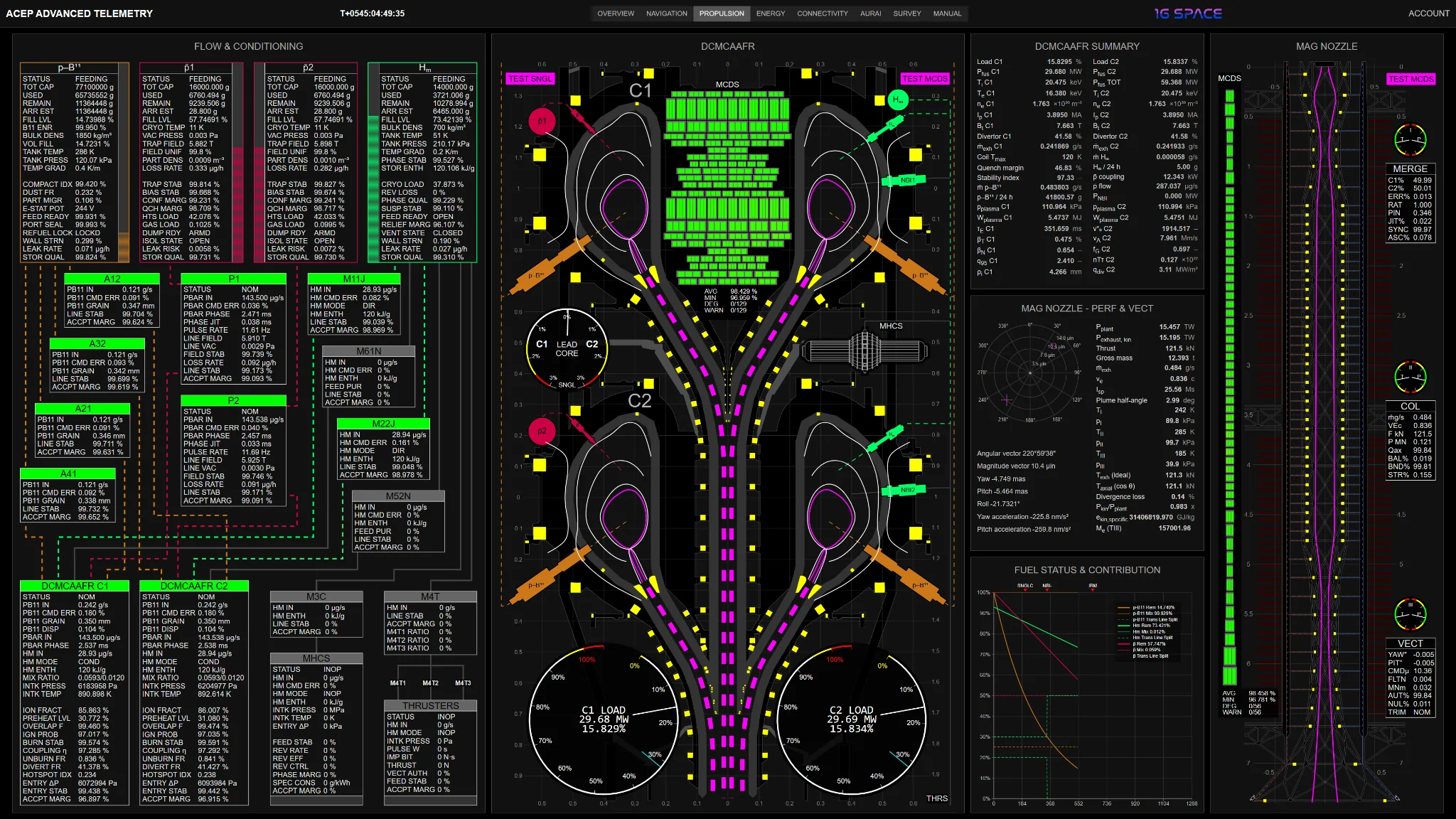
The Propulsion domain presents the full propulsion-material, reactor, and exhaust-control chain. It tracks p-B11 storage and feed, antiproton containment and transfer, metallic hydrogen support paths, injector-line stability, core-feed acceptance, DCMCAAFR state, plasma geometry, magnetic-coil health, thrust output, nozzle collimation, vectoring, and fuel inventory evolution.
At the center of the domain is the Dual-Core Magnetically Confined Antiproton-Augmented Fusion Reactor (DCMCAAFR). The page separates feed readiness from reactor behavior and separates reactor behavior from nozzle performance, making it possible to follow how stored material becomes conditioned feed, how feed becomes confined plasma, how plasma becomes directed exhaust, and how that exhaust maps into thrust, vectoring, and propellant economy.
- Flow & Conditioning for p-B11, pbar1, pbar2, and metallic hydrogen storage, including total capacity, used mass, remaining mass, arrival reserve estimate, fill level, tank temperature, tank pressure, cryogenic load, trap field, vacuum pressure, confinement margin, and storage-quality indicators.
- Transfer-line state for p-B11 branches A12/A32/A21/A41, antiproton channels P1/P2, metallic-hydrogen conditioning branches M11J/M22J, NBI support branches M61N/M52N, MHCS feed M3C, and M4T maneuver-thruster feed.
- Core-consumer telemetry for DCMCAAFR C1 and C2, including p-B11 input, antiproton input, metallic hydrogen input, mixture ratio, intake pressure, intake temperature, ion fraction, preheat level, overlap factor, ignition probability, burn stability, coupling efficiency, unburned fraction, divertor fraction, hotspot index, and acceptance margin.
- DCMCAAFR cross-sectional reactor view showing dual-core geometry, confined plasma contour, magnetic flux surfaces, injector overlays, core-load gauges, lead-core differential, merged exhaust column, NBI interfaces, MHCS interface, and antiproton injection points.
- MCDS coil health matrix for reactor and nozzle coil systems, with field stability, thermal margin, current balance, average coil health, minimum coil health, degraded-unit count, warning count, quench margin, cryogenic utilization, and field-imbalance context.
- DCMCAAFR Summary table for per-core fusion power, ion/electron temperature, electron density, plasma current, toroidal field, divertor fraction, exhaust mass flow, plasma pressure, stored plasma energy, energy confinement time, beta, q95, collisionality, Alfven speed, Greenwald fraction, triple product, and divertor heat flux.
- Mag Nozzle Performance & Vectoring for plant power, exhaust kinetic power, thrust, gross mass, exhaust mass flow, effective exhaust velocity, ISP, plume half-angle, merge/collimation/vectoring region pressure and temperature, axial thrust, divergence loss, kinetic-power ratio, yaw, pitch, roll, lateral acceleration, and vectoring trim.
- Fuel Status & Contribution curves showing remaining p-B11, metallic hydrogen, and antiproton inventories; instantaneous mixture contribution; transfer-line split; current mission-day marker; SNGLC, NBI-, and IRM propulsion markers; and reserve-margin behavior over mission time.
- Magnetic Nozzle panel for plasma envelope symmetry, collimation quality, regional thermodynamic gauges, merge telemetry, collimation telemetry, vectoring telemetry, local coil diagnostics, coolant paths, and metallic-hydrogen thruster-interface status.
Energy
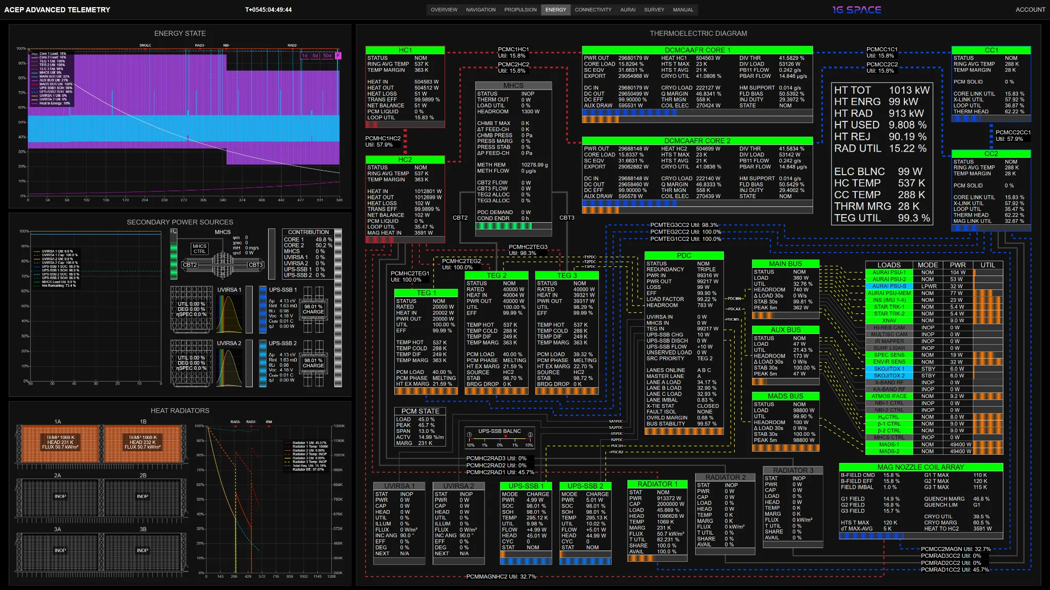
The Energy domain presents ACEP's electrical and thermal architecture as one coupled spacecraft power system. It resolves the path from DCMCAAFR heat production through hot-circuit transport, thermoelectric conversion, radiator rejection, power distribution, storage buffering, secondary sources, and final load consumption.
The page is designed to make energy coherence visible across mission phases. During powered cruise it emphasizes reactor-derived heat recovery, radiator load, TEG utilization, PDC dispatch, and MADS bus demand. During later regimes it exposes thermal down-staging, radiator retirement, UPS-SSB behavior, MHCS contribution, UVIRSA availability, and the transition toward lower-power post-reactor and hibernation states.
- Energy State history for DCMCAAFR core loads, TEG utilization, MHCS utilization, MAIN/AUX/MADS bus use, UPS-SSB state of health, UVIRSA output, Heat-to-Energy fraction, mission-phase power transitions, radiator-retirement markers, IRM, arrival, and hibernation boundary.
- Secondary Power Sources for UVIRSA 1/2, UPS-SSB 1/2, MHCS, real-time source contribution, 60-minute secondary-power trends, UVIRSA degradation/capacity, UPS-SSB SOC/SOH, MHCS load, metallic hydrogen remaining, and source-share attribution.
- UPS-SSB detail including charge/discharge state, stored energy, health ceiling, internal resistance, open-circuit voltage, charge/discharge rate, Joule heating, cycle count, temperature, utilization, flow, headroom, and power-sharing imbalance.
- Heat Radiators panel for three radiator trains, six radiator panels, per-panel temperature, thermal headroom, radiative flux density, utilization, temperature history, radiator efficiency, total radiative requirement, RAD3- and RAD2- transitions, IRM marker, and post-spool-down behavior.
- Thermoelectric Diagram showing active thermal and electrical paths from DCMCAAFR cores through hot circuits, cold circuits, phase-change thermal transport, TEG1/TEG2/TEG3, radiators, MHCS, UVIRSA, UPS-SSB, PDC, and downstream buses.
- DCMCAAFR energy blocks for core power output, core load, single-core equivalent load, export power, hot-circuit heat, HTS maximum and average temperature, cryogenic utilization, internal DC conversion, auxiliary draw, thermal margins, divertor load, p-B11 flow, antiproton flow, metallic-hydrogen support, field bias, and injector duty.
- Hot Circuit and Cold Circuit telemetry for ring-average temperature, heat input/output, transfer efficiency, net balance, PCM liquid/solid fraction, loop utilization, magnetic-nozzle heat coupling, thermal headroom, and cross-link utilization.
- TEG telemetry for rated output, heat input, electrical output, utilization, conversion efficiency, hot/cold temperature, temperature differential, temperature margin, PCM load, phase state, heat-exchanger margin, source selection, thermal stability, and ceramic-bridge drop.
- PDC, bus, and load tables for power in/out, conversion loss, headroom, lane state, lane share, UVIRSA input, MHCS input, TEG input, UPS-SSB charge/discharge flow, unserved load, bus stability, MAIN/AUX/MADS bus demand, peak loads, and individual subsystem consumers.
Connectivity
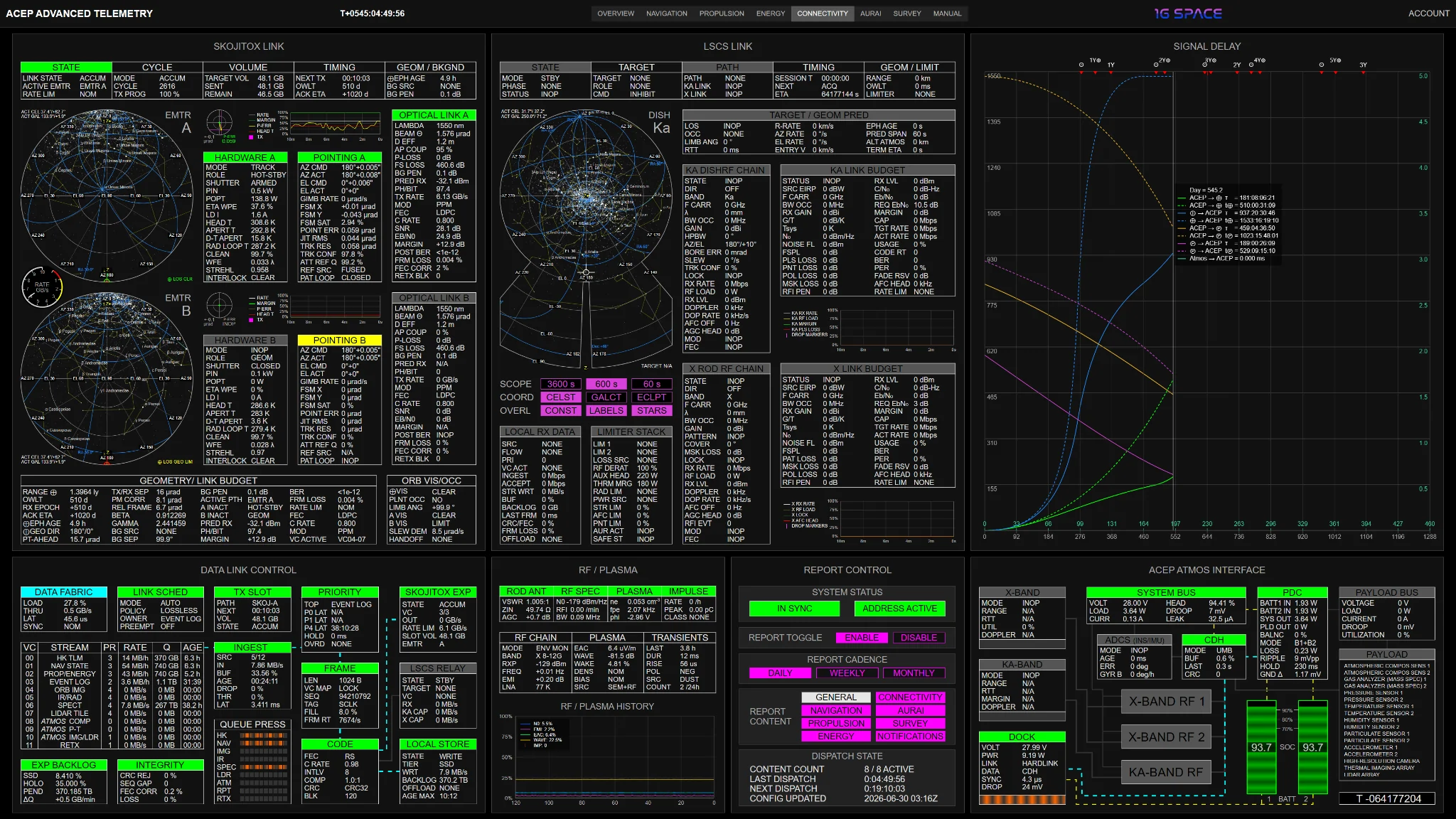
The Connectivity domain presents ACEP communication as a complete data-routing and link-geometry system. It includes the SKOJITOX deep-space optical link, local LSCS RF communication, internal telemetry routing, report generation, signal-delay analysis, RF/plasma interaction diagnostics, and the ACEP Atmos electrical/data/RF interface.
The domain separates data movement from link closure. Users can inspect whether telemetry is being generated, admitted, queued, framed, coded, stored, retransmitted, exported through SKOJITOX, relayed locally through LSCS, or constrained by geometry, pointing, occultation, plasma/fade effects, storage pressure, AFC headroom, power, or thermal margin.
- SKOJITOX Link for deep-space optical communication state, deterministic transmission cycle, assigned data volume, sent/remaining volume, next TX, OWLT, ACK ETA, Earth ephemeris age, background penalty, active emitter selection, and rate-limiting condition.
- Emitter A/B PAT hemisphere displays with local azimuth/elevation geometry, spacecraft body-axis markers, actual boresight, Earth line-of-sight state, celestial/Galactic pointing readouts, emitter trend graphs, residual pointing error, and active transmission bands.
- SKOJITOX hardware and optical-link budget blocks for laser power, wall-plug efficiency, wavefront error, Strehl ratio, aperture temperature, pointing command/actual state, FSM residuals, jitter, tracking confidence, beam divergence, free-space loss, background penalty, photons per bit, SNR, Eb/N0, BER, frame loss, FEC correction, and retransmission demand.
- Data Link Control for AURAI-managed data fabric, ingest, virtual channels, queue pressure, frame generation, coding, FEC, CRC, compression, local SSD/HOLO backlog, SKOJITOX export, LSCS relay, and local store state.
- LSCS Link for local communication with ACEP Atmos, including Ka-band dish state, X-band rod state, target assignment, session timing, range, local OWLT, line-of-sight geometry, limb occultation, Ka/X RF-chain status, link budgets, receive rates, fade reserve, AFC headroom, and local RX data acceptance.
- RF / Plasma auxiliary diagnostics derived from the rod antenna and RF front-end, including RF noise floor, EMI, electric-field pickup, plasma-wave activity, wake coupling, spacecraft potential proxy, transient impulse rate, MADS event coupling, stellar flare coupling, and local RF cleanliness.
- Signal Delay graph showing one-way light time between ACEP and Earth, Earth and ACEP, ACEP and Proxima b, Proxima b and ACEP, and ACEP Atmos to ACEP during descent, with ship proper time and remote-frame timing separated.
- Report Control for subscription report dispatch: sync state, address state, enable/disable control, daily/weekly/monthly cadence, selectable content domains, content count, last dispatch, next dispatch, and configuration update timestamp.
- ACEP Atmos Interface showing docked hardline support before release, battery-fed operation after separation, PDC state, System Bus, Payload Bus, X-band RF, Ka-band RF, ADCS, CDH, payload manifest, electrical paths, data paths, dock state, and post-release RF telemetry routing.
AURAI
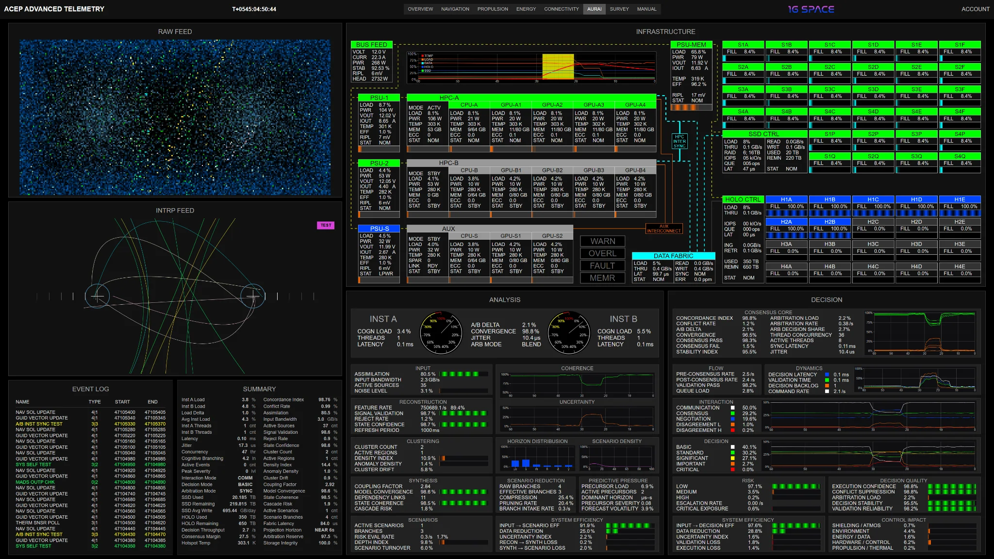
The AURAI domain exposes the spacecraft's autonomous analytical and control architecture. AURAI reconstructs the spacecraft-environment state from multisource telemetry, models cross-system dependencies, detects anomaly precursors, evaluates risk, arbitrates redundant analytical outputs, and produces validated control decisions.
The page presents AURAI as a layered control system rather than a single status indicator. Raw signal activity, interpreted system structure, event chronology, compute infrastructure, analytical pipeline, consensus state, decision dynamics, risk classification, and control-domain impact are separated into dedicated panels so that cognitive load, hardware state, analytical stress, and validated output quality can be assessed independently.
- Raw Feed for direct AURAI signal-field activity, dual-instance symmetry, cross-instance interaction, decision-path traffic, ship-state regions, sensor input activity, persistent structures, and anomaly precursors.
- INTRP Feed for structured interpretation of the same processing field, including core load rings, synchronization lines, decision structures, subsystem sectors, filtered sensor returns, persistent fault indicators, and active inter-instance behavior.
- Event Log for AURAI-detected or scheduled events, event identifiers, domain classification, severity, start/end interval, pending state, environmental interactions, subsystem activity, and planned operations.
- Summary panel for instant AURAI state: Instance A/B load, load delta, thread count, latency, jitter, concurrency, cognitive branching, active events, peak severity, interaction mode, decision mode, arbitration mode, storage state, decision throughput, consensus margin, concordance, conflict rate, assimilation, validation, state confidence, cascade risk, and storage integrity.
- Infrastructure panel for the physical compute substrate: BUS FEED, PSU-1/2/S/MEM, HPC-A, HPC-B, AUX compute, CPU/GPU blocks, SSD control, HOLO control, storage media occupancy, data-fabric throughput, internal synchronization, power quality, thermal state, ECC, and infrastructure annunciators.
- Analysis panel for the internal cognition pipeline from input assimilation through reconstruction, clustering, synthesis, scenario generation, predictive pressure, uncertainty, coherence, branch reduction, precursor load, forecast volatility, and system efficiency.
- Decision panel for validated output behavior, including consensus core, concordance index, conflict rate, convergence, arbitration load, queue load, decision latency, validation time, command rate, interaction distribution, decision class distribution, risk distribution, execution confidence, validation reliability, and control impact.
- Control-domain impact separation for shielding/Atmos, environment, energy/data, hardware/control, and propulsion/thermal domains, allowing the user to see which spacecraft systems are being affected by current AURAI decisions.
Survey
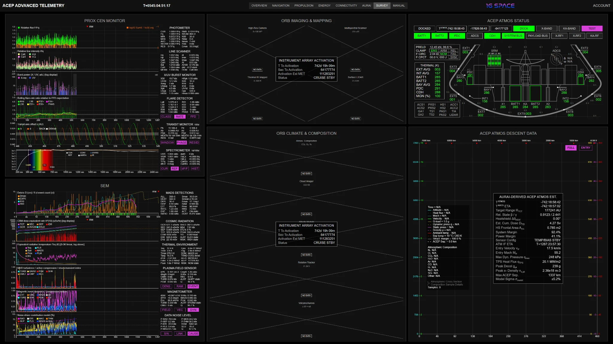
The Survey domain aggregates the scientific measurement stack across cruise, arrival, orbital operations, and ACEP Atmos deployment. It separates stellar monitoring, space-environment measurement, orbital imaging, climate and composition sensing, probe status, and descent telemetry into phase-dependent science domains.
The page allows Proxima Centauri activity, interstellar and local environment conditions, orbital target acquisition, atmospheric composition, thermal mapping, LIDAR, probe health, and entry dynamics to be evaluated in relation to the mission timeline. During cruise the emphasis is on the star and the surrounding environment; after orbital insertion the emphasis shifts toward Proxima b mapping, atmospheric analysis, and ACEP Atmos descent.
- Proxima Centauri Monitor with Photometer, Line Scanner, X/UV Burst Monitor, Flare Detector, Transit Monitor, and Spectrometer channels for broadband flux, flare excess, flare-energy index, chromospheric line response, X/UV burst hardness, flare-frequency distribution, transit-window geometry, spectral residuals, and activity history.
- Photometric and spectroscopic monitoring for H alpha, H beta, Ca II H/K, broadband UV/visible/IR partitioning, effective-temperature proxy, color-index proxy, line excess, chromospheric activity, flare class, rolling flare rates, and cumulative flare population.
- SEM stack for MADS detections, cosmic radiation, thermal environment, plasma field, magnetometer state, and data-noise level, covering debris-event size and outcome, dose-equivalent radiation, shielded exposure, environmental heat flux, plasma density, relativistic ram interaction, magnetic-field decomposition, current-sheet activity, S/N, link noise, and disturbance attribution.
- Orbital Imaging & Mapping for high-resolution camera acquisition, multispectral scanner state, thermal IR mapping, and surface LIDAR, supporting visible-band imaging, spectral contrast, brightness-temperature mapping, topographic profiling, and surface-reconnaissance context.
- Orbital Climate & Composition for atmospheric composition, cloud imaging, albedo mapping, rotation tracking, and volcano/aurora detection, including limb/nadir spectroscopy, cloud/aerosol characterization, reflectance mapping, rotation-period constraints, thermal anomalies, UV auroral signatures, and atmospheric-magnetospheric coupling indicators.
- ACEP Atmos Status for probe phase, dock/release state, timers, active link mode, health annunciators, battery state, PDC, ADCS, CDH, System Bus, Payload Bus, RF chains, separation system, SRM state, heat-shield thermal sensors, equipment-bay thermal state, payload sensors, and structural schematic context.
- ACEP Atmos Descent Data for full and entry-focused views of altitude, velocity, dynamic pressure, G-load, Mach number, heat flux, static pressure, density, ambient temperature, bay temperature, structural margin, ACEP separation, telemetry validity, composition summary, atmospheric cross-section, and composition-sample reliability.
- Phase-dependent measurement logic, with cruise monitoring, final approach activation, orbital science acquisition, ACEP Atmos deployment, atmospheric interface, maximum heat flux, maximum dynamic pressure, terminal coherent-data-loss marker, and retained final descent dataset.
Manual

The Manual is the full technical reference layer for ACEP Advanced Telemetry. It is an extensive operational document, not a short guide or brief product note. Every telemetry page, panel, indicator, acronym, unit, control, graph, table field, and displayed parameter is described with its operational meaning, reference frame, unit context, subsystem relationship, and interpretation logic.
The Manual is structured around the same domains as the telemetry portal: Overview, Navigation, Propulsion, Energy, Connectivity, AURAI, and Survey. It also includes introductory system context, an acronyms and units reference, the ACEP Operator's Quick Reference Panel, and the ACEP Operator's Calculation Tool. This makes the Manual usable both as a complete read-through document and as an active reference while inspecting the portal.
- Complete parameter-level documentation for all displayed telemetry values across Overview, MSAD, Navigation, Propulsion, Energy, Connectivity, AURAI, Survey, ACEP Atmos, Report Control, QRP, and CAL.
- Acronyms & Units section covering spacecraft systems, astronomical frames, engineering units, telemetry abbreviations, coordinate terms, propulsion notation, communication parameters, and scientific-instrument labels.
- Multi-lingual Manual support, with additional language coverage planned over time.
- ACEP Operator's Quick Reference Panel for rapid lookup of parameter definitions, subsystem terms, units, aliases, acronyms, engineering meaning, and operational notes directly from the Manual content.
- QRP scope control with LOCAL, MEDIUM, and BROAD search modes, allowing a result to return a precise definition, a containing parameter block, or the larger subsystem context around the match.
- ACEP Operator's Calculation Tool for unit conversion, dimensional validation, material-density checks, p-B11, metallic hydrogen, and antiproton storage calculations, relativistic interpretation, signal-delay checks, 1 g transfer profiling, constants, scalar math, and verification calculations.
- Manual navigation tree and domain menu aligned with the portal's telemetry pages, allowing direct movement from high-level domain sections to individual panels and parameter groups.
- Interpretation support for long-duration review, including how to read graph axes, proper-time versus Earth-frame timing, mission-phase markers, subsystem margins, source weights, warning states, confidence values, and cross-domain dependencies.
Access model: This is a digital subscription product. Active subscribers receive access to the protected ACEP Advanced Telemetry portal; no physical item is shipped.
The subscription supports both brief mission-status checks and detailed technical review of ACEP as a continuously monitored spacecraft system.